New Functional Applications of ZEISS CALYPSO in the New Energy Vehicle Industry
 02/17 2025
 448
448
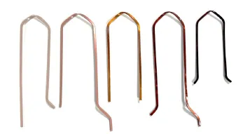
In the realm of new energy vehicle motor design and manufacturing, the stator stands as a pivotal component. The hairpin winding within the stator has garnered significant attention due to its distinctive structure and superior performance. By integrating a U-shaped coil design, the hairpin winding effectively boosts the motor's power density and efficiency while simultaneously reducing its size and weight, thereby enhancing the motor's overall performance.
Given the flexible structure of individual hairpins and the delicate insulating varnish coating, conducting dimensional inspections using contact coordinate measuring machines proves extremely challenging. Even when employing an optical sensor such as LineScan, adjustments must be made to accommodate the coating's thickness, color, and light transmission, and special fixtures are necessary to complete the measurement process.
The new version of ZEISS CALYPSO optimizes the LineScan sensor, enabling more efficient inspections. Note: The functions mentioned below are exclusive to ZEISS CALYPSO 2023 or later versions and are compatible with LineScan sensors.
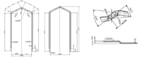
Typical Inspection Items
- Pin spacing
- Angular deviation
- Twist deviation
- Stripped wire length
- Straightness
- Overall height
- Complete head geometry
- Unwound length
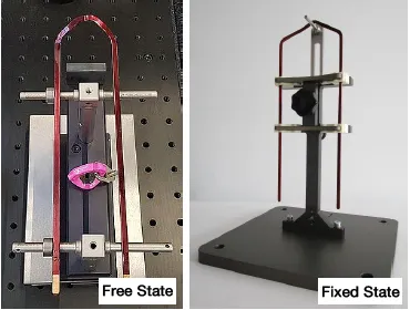
Clamping Methods
Based on customer inspection requirements, there are generally two clamping methods:
- Free State (left image): Fixes only one side of the hairpin, leaving the other side unconstrained.
- Fixed State (right image): Fixes both pins in place (e.g., using fixtures at their theoretical positions).
For measurement convenience, it is recommended to position the hairpins vertically. However, if special fixtures are available, they can be placed vertically or horizontally as needed.
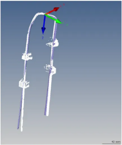
Coordinate System Establishment
Since the hairpin is a 3D curved part, it is advisable to employ a point set measurement strategy to collect each reference point. Establish the coordinate system through iterative 3D best-fit or RPS methods, minimizing errors caused by part deformation.
PCM statement: baseSystem().valueA<0.01
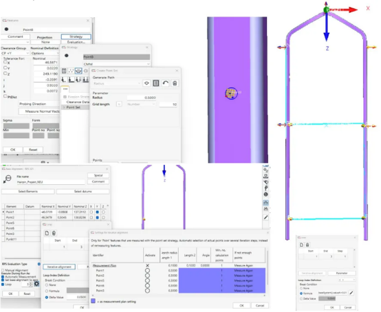
LineScan Acquisition Settings
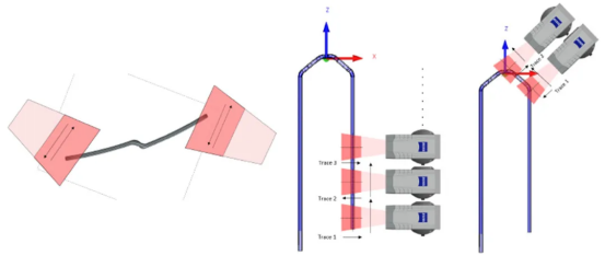
To minimize noise from the reflection of various hairpin coatings, place the LineScan sensor in front of the workpiece and configure scan settings using the "Live Image" window (introduced in ZEISS CALYPSO 2023).
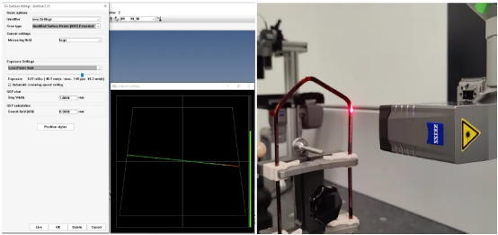
Simultaneously set scans at different angles to cover the required inspection areas of the part.
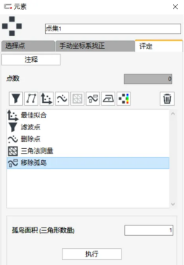
Point Cloud Data Processing
Utilize filtering and island removal functions to optimize the point cloud data acquired by LineScan (new feature in ZEISS CALYPSO 2022).
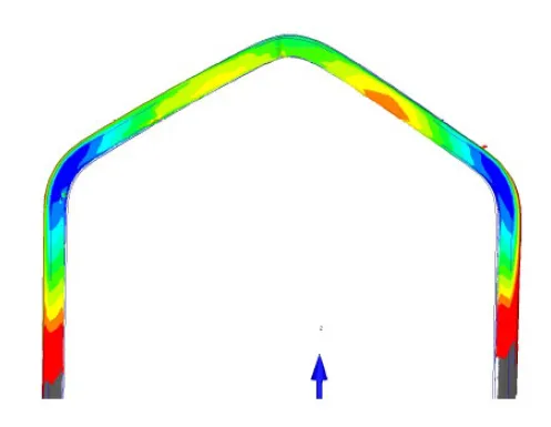
Inspection (Head Shape)
Comparing point cloud data with the product model generates a faster color difference map, clearly and intuitively showing where product deviations are distributed, aiding in the improvement of product processes (new feature in ZEISS CALYPSO 2023).
-
![]()
Zeekr and Lynk & Co. Merge: The Era of Automotive Industry "Integration" Dawns
-
![]()
iPhone 16e Launches Amidst Sharp Price Hike and Mixed Reception!
-
![]()
Is India Once Again Extorting Samsung? Samsung Reaches Breaking Point, Preferring Shutdown Over Compromise
-
![]()
Lingbao CASBOT Secures Over 100 Million Yuan in Angel Funding, Speeding Up Mass Production
-
![]()
Teeni.AI and China Telecom Forge Strategic Partnership, Ushering in the Era of AI Agents!
-
![]()
Qualcomm's Market Share at Risk? Apple Unveils iPhone 16e with In-House 5G Baseband Chip
-
![]()
Tesla's 'Shandong Strategy'
-
["Focus"] The Global Soft Robotics Market: Poised for Sustained Rapid Growth Amid Strategic Expansion by Key Manufacturers


